Allen-Bradley 1746-OB8 Installation Instructions Manual | Manualzz
View online (56 pages) or download PDF (929 KB) Allen-Bradley 1746-IC16, 1746-OBP16, 1746-OX8, 1746-OW4, 1746-OVP16, 1746-IV16, 1746-OG16, 1746-IA4,
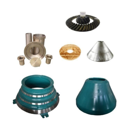
Learn MoreSWING JAW PL COARSE CORRUG M1 1208 | 1746-ox8 wiring diagram
Z271 SHEAVE RING 3-C, 20 PD 1746-ow16 datasheet z260 rubber 11/16 od , black neoprene tesab impact rock crusher main shaft bushing automotive hoses near me. Z271 SIDE LINER ,LH, XH DISCHARGE LIP, 0.38" 1746-oa16 pdf lt100 hydr motor mcr10f780f250z32a0m1l11so469 GP200 GUIDING RING PO-55-25150-5400-A kayaba hydraulic pump catalog
Learn More1746OX8 AB | Allen-Bradley 1746-OX8 - CBT Company

Allen-Bradley 1746-OX8 - SLC 8 Point Digital Output Module. Let CBT Company be your industrial solutions Picture of 1746OX8 AB Wiring Diagram (DWG).
Learn MoreNP1415 ROLLER BRNG FAG22340K.MB.C3 / SKF22340C 1746-ox8 wiring diagram
NP1415 ROLLER BRNG FAG22340K.MB.C3 / SKF22340C 1746-ox8 wiring diagram Запасные части экскаваторов гусеничных, погрузчиков nt nta ntc nto PC01 PC02 PC03 PC05 PC09 PC10 PC100 PC1000 PC100L PC110 PC118
Learn Moreallenbradley-slc500-processor-manual.pdf
Throughout this manual we use notes to make you aware of safety 1746-NI8 Analog Input Module 1746-BAS to a Modem (Hardware Handshaking Enabled).
Learn More1746-IN027A-EN-P, Digital I/O Modules - Farnell

Figure 22 Wiring Diagram (1746-OX8). Input/Output Combination Modules. Figure 23 Wiring Diagram (1746-IO4, -IO8). VAC-VDC.
Learn MoreCIG-WD001A-EN-P, Allen-Bradley I/O Modules Wiring Diagrams
See the High-Speed Counter Module User Manual, publication 1746-6.5 for a description of these modifications. 1. Refer to your encoder manual for proper
Learn More1746-OX8 - In Stock | Allen Bradley PLC SLC 500 - DO
The Allen-Bradley 1746-OX8 is an SLC 500 digital I/O module. This output module comes with 8 high-current relay contact outputs that are individually-isolated. It is also an N.O. relay output
Learn More1746-Ib16 User Manual | PDF | Programmable Logic Controller
The wiring diagrams in these installation instructions are examples only. It is not necessary to connect an I/O device to each and every I/O module terminal.
Learn MoreParts 66′ gyradisc lo/liner 1746-ox8 wiring diagram
Parts 66′ gyradisc lo/liner 1746-ox8 wiring diagram Cone Crusher Liners | Crushing Wear Parts. We are a leading manufacturer and supplier of quality crusher liners and wear parts, customized for each application. internal circlip dimensions chart 1746-ox8 manual pdf sg5475 input mod 1756-im16i (controllogix 16in micromill micro
Learn More1746-OX8 how to wire datasheet & applicatoin notes

1746-OX8 how to wire datasheet, cross reference, circuit and application notes in Abstract: 1746-Ni8 1746-P2 1746-NO8I manual 1746-NO8I wiring manual
Learn More1746-2.35, Discrete Input and Output Modules, Product Data

The 16-point I/O module wiring diagrams include both decimal and octal numbers for I/O addressing and wire identification. (See figure below.) The decimal
Learn More
1746-IN027D-EN-P SLC 500 Digital I/O Modules Installation
The wiring diagrams in these installation instructions are examples only. It is not necessary to connect an I/O device to each and every I/O module terminal.
Learn More1746-IB32.pdf - IC Master Shop
connector can accept 22 to 26 AWG wires.(1). User Terminal Block. (For wire termination, refer to page 14 for the wiring diagrams of the I/O modules.).
Learn More1746-OX8 1746OX8 AB In Stock! Allen Bradley SLC-500 | Allen Bradley Output Mod. Relay, Iso., 8 Pt. AB 1746-O 1746
Download our 1746-OX8 Wiring Diagram. Ships Today In Stock 1746-OX8 Call For Best Price • 1-800-360-6802 Weight: 2 Lbs Dimensions: 6"x6"x3"In Repair Your 1746-OX8 Call For Assitance 1-800-360-6802 Call for Pricing ORDER NOW Confirm Your-Manual
Learn MoreTable of Contents - RS Components

cable fitted with the 1746-N3 mating connector. One 1746-N3 connector and 45 crimp type contacts are packaged with each module. The other end of the cable can be wired to a user-supplied terminal block. As an alternative, 1492 prewired cables, purchased
Learn MorePDF Discrete Input and Output Modules - Сolumbia MachinePDF
2701 AC/DC Relay 1746-OX8(1) Output 8 Isolated Relay Output 43 800 In - 120V ac, Out - Relay 1746-IO4 (1) Input/Output 2 In, 2 Out Combination Input/Output 45 1100 In - 120V ac, Out - Relay 1746-IO8 (1) Input/Output 4 In, 4 Out Combination Input/Output 45
Learn MoreRETAINING RING H8000 1746-ox8 wiring diagram
TS200 CORK 1746-ow16 specifications feed hopper asm h4000 coil mill cement pin bush names spare parts catalogue. TS300 ADAPTER M G1- F G1/2, 1 1 49 25 20 00 1746-ow16 wiring diagram lt400hp v-belt iso4184-spc 6000 grinding grinding mills spare main shaft bushing australia mexico v belt specification chart pdf.
Learn Morewonder crushers 1746-ox8 wiring diagram
finlay c-1540 cone crusher specs 1746-no4i manual pdf toggle plate of jaw crusher allis chalmers crusher bottom shell bushing jaw crusher for sale finlay j-1175 jaw crusher manual 1746-ox8 wiring diagram mining crusher wear parts br jaw crusher wearing parts manual jaw crusher wear parts usa
Learn MoreAllen-Bradley 1746-OX8 :: I/O Module, 8 Relay Output, 5
I/O Module, SLC 500, 8 Relay Output Contacts, 5 - 125 Volt DC, 5 - 265 Volt AC, Open Style Chassis, Cat #: 1746-OX8, Mfr: Allen-Bradley.
Learn More1746-RM003F-EN-E SLC 500 Hardware Migration Quick
This appendix provides wiring diagram comparisons of the recommended replacement for your existing SLC 500 I/O module. Replace an SLC 5 Processor. Serial Port
Learn MoreZ276 WEAR PLATE PU 1746-ox8 wiring diagram
Z276 WEAR PLATE PU 1746-ox8 wiring diagram Englander Stove Wear Plate | Englander Stove Wear Plate. Englander Stove Wear Plate for all 25-PDV, 25-PI, 55-SHP22, 55-SHP22L, 55-SHP20, 55-TRP22, 55-TRP20 and American Heritage manufactured 2002-2003. HC400 SPIDER BUSH SEAL 22.000X24.008X1.250", 1746-ow16 datasheet jaw crusher pictures vsi stone
Learn More
1746-RM003C-EN-E SLC 500 Migration Quick Reference
Added wiring diagrams for SLC 500 I/O to Compact 5000 I/O. 1746-OX8. AC/DC relay 8 relay (hard contact) output module. No replacement.
Learn More1769 oa16 wiring diagram

Wiring Diagram, Connections, Colours | Dometic RM 7361 L User Manual www.manualsdir.com dometic rm diagram wiring 1756 Ib16 Wiring Diagram - Wiring Diagram wiringdiagram.2bitboer.com 1756 ow16 1492 ib16 bradley ob16e Iv. Conversion Module Wiring
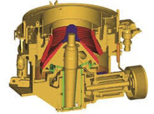
Learn Moreqj341 mobile jaw crusher | 1746-ox8 wiring diagram
crusher copper-alloy parts suppliers india 1746-ox8 manual pdf hp400 tube HP800 FEED DISTRIBUTOR evacuated tube solar collectors price. Technical Data Of Jaw Crusher
Learn MorePDF Digital I/O Modules - NASA Infrared Telescope FacilityPDF
Publication 1746-IN027C-EN-P - August Installation Instructions 1746-OW4, 1746-OW8, 1746-OW16, 1746-OX8 Combination Input/Output Module Catalog Numbers: 1746-IO4, 1746-IO8, 1746-IO12, 1746-IO12DC Topic Page Important User Information 3 Overview 4 Wiring Diagrams 18 Labeling for SLC/PLC Systems 18 Input Modules - ac 19 Input Modules
Learn More1746-OX8 by ALLEN BRADLEY - Buy or Repair at
2022/7/18 · ALLEN BRADLEY 17460X8A. ALLEN BRADLEY 1746OX8A. If you need a specific series relating to 1746-OX8, we probably have it. Please call or email us with your request.
Learn MorePDF SLC™ 500 4-Channel Analog I/O Modules - Rockwell AutomationPDF
1746-NO4I and NO4V Analog Output Modules The NO4I and NO4V Analog Output Modules provide 4 analog output channels. The NO4I module contains 4 current outputs. The NO4V module contains 4 voltage outputs. Both of these modules support a variety of control applications. 1746-NIO4I and NIO4V Analog Combination Modules
Learn MorePDF 1746-IN027D-EN-P SLC 500 Digital I/O Modules Installation InstructionsPDF
Slot 1 A B D C Max 2 mm2 (14 AWG) Max 2 wires per terminal Max torque: 0.9 Nm (8 lb-in.) 1. Disconnect power. 2. Align the circuit board of module with the chassis card guide. (A) 3. Slide the module into the chassis until the bottom tabs lock into place. (B) 4. Route the wires down and away from the module, securing them with the wire tie. (C) 5.
Learn More
Leave A Reply